- Your cart is empty Browse Shop
Crosshole and Downhole Seismic
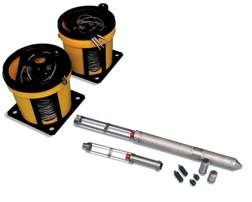
The Crosshole Seismic (CS) system and method determine shear and compressional wave velocity versus depth profiles. From these measurements, parameters, such as Poisson’s ratios and moduli, can be easily determined. In addition, the material damping can be determined from CS tests. These dynamic soil and rock properties are often utilized for earthquake design analyses necessary for certain structures, liquefaction potential studies, site development, and dynamic machine foundation design. The most complete version of this downhole system, as manufactured by Olson Instruments, is comprised of a borehole source capable of generating shear and compressional waves and a pair of matching three component triaxial geophone receivers. These instruments are lowered to the same depth in boreholes set at ~ 10 ft (3 m) apart in a line. The instruments are coupled to the side of the grouted borehole inclinometer casing, allowing for the detection of shear and compressional waves as they pass between the receivers.
Impact Echo (IE)
Impact Echo (IE) investigations are performed to assess the condition or thickness of slabs, beams, columns, walls, pavements, runways, tunnels, and dams.
The Impact Echo (IE) system is designed to determine the condition and thickness of concrete, wood, stone, and masonry structural members when voids, honeycomb, and/or cracks are suspected. IE investigations can also be performed to predict the strength of early age concrete if the member thickness is known. Lastly, the IE method will provide information on the depth of a flaw or defect, in addition to mapping its lateral location and extent. An advantage of the IE method over the Ultrasonic Pulse Velocity (UPV)
method is that only one side of the structure needs to be accessible for testing.
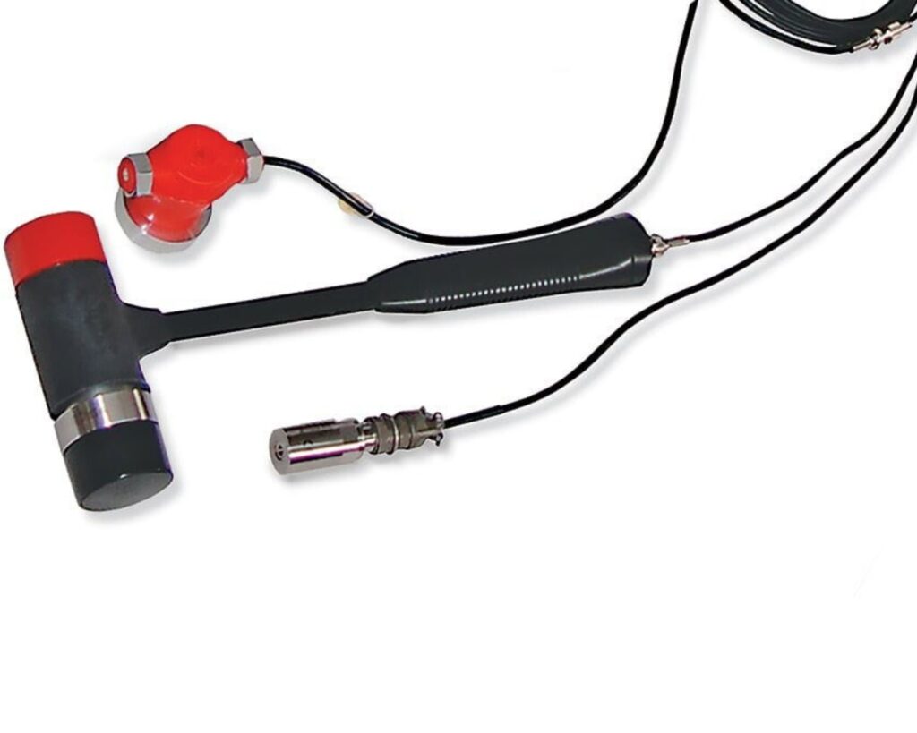
Pile Integrity Testing
The Sonic Echo-Impulse Response test method (also known as the Pile Integrity Test, or PIT) is designed to determine the length and integrity of foundations when the top or part of the upper side of the foundation is accessible. This method can be used on both new and existing foundations and is performed by impacting the foundation and recording echoes from a defect or the foundation bottom with a nearby receiver(s). This Pile Integrity Test method works best for columnar type foundations such as piles and drilled shafts, but has also been used successfully on mat foundations, abutment walls, and similar structures. Sonic Echo-Impulse Response is applicable on concrete, wood, and round steel pipe foundations.
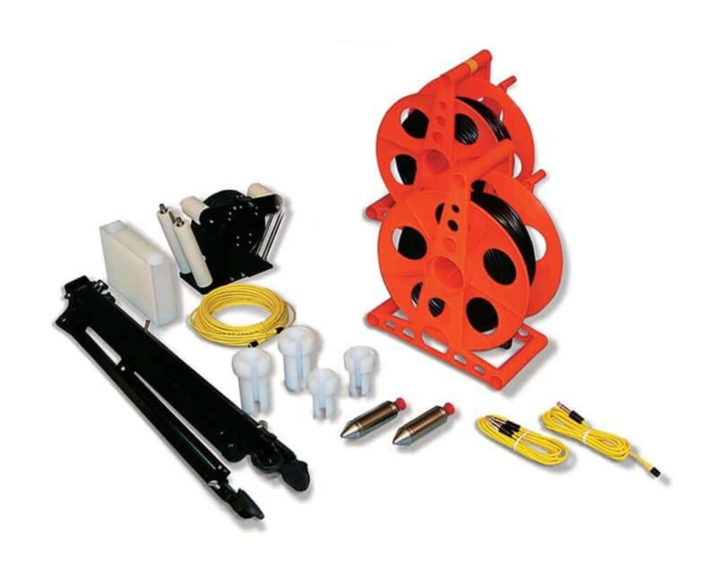
Parallel Seismic
Parallel Seismic is more accurate, more versatile than other non-destructive surface techniques for determination of unknown foundation depths.
Parallel Seismic (PS) systems are designed to determine the length and integrity of foundations when the top is not accessible or when the pile is too long and slender to test with echo techniques, or below a buried pile cap. Ultimately, Parallel Seismic testing provides information concerning the length and compressional velocity of foundations and can be used on concrete, wood, masonry, and steel foundations. This method also provides information about the soil below the foundation bottom.
Note: Parallel Seismic requires the installation of a grouted, cased borehole.
Crosshole Sonic Logging
The Crosshole Sonic Logging system is the most accurate and reliable technique for assessing the integrity of deep foundation elements constructed on-site from concrete or grout. The system is designed for Quality Assurance (QA) testing of newly placed critical drilled shaft foundations and auger cast piles, but can also be applied to slurry walls, mat foundations, and mass concrete pours. Using water-filled access tubes, CSL testing provides assurance that the foundation concrete is sound with no defects such as soil intrusions, necking, sand lenses, voids, etc.
Where defects exist, the extent, nature, depth, and approximate lateral location of the defects can be determined with the Crosshole Sonic Logging method and further refined with Tomography Imaging Solution, which is sold by Olson Instruments. (Note: Optional Tomo software is available for the CSL, UPV, and CS/DS add-on test methods)
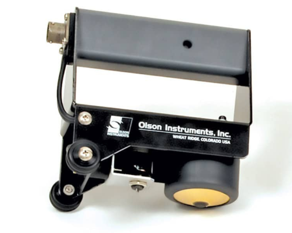
Slab Impulse Response
The Slab Impulse Response (SIR) system is designed to identify subgrade voids below slabs-on-grade less than two feet thick. In addition, the Slab IR test method can be used on other concrete structures to quickly locate areas with delaminations or voids in the concrete, if the damage is relatively shallow. Slab IR can be performed on reinforced and non-reinforced concrete slabs as well as asphalt or asphalt-overlay slabs.
The Slab IR testing method is often used in conjunction with GPR for subgrade void detection and mapping. Collecting Slab IR data at multiple, densely spaced locations can improve the conclusions by mapping relative areas of higher and lower mobility. Relatively low mobility (velocity/force) and flexibility (displacement/force) qualitatively indicates that such an area appears to be more solidly supported than an area with relatively high mobility and flexibility.
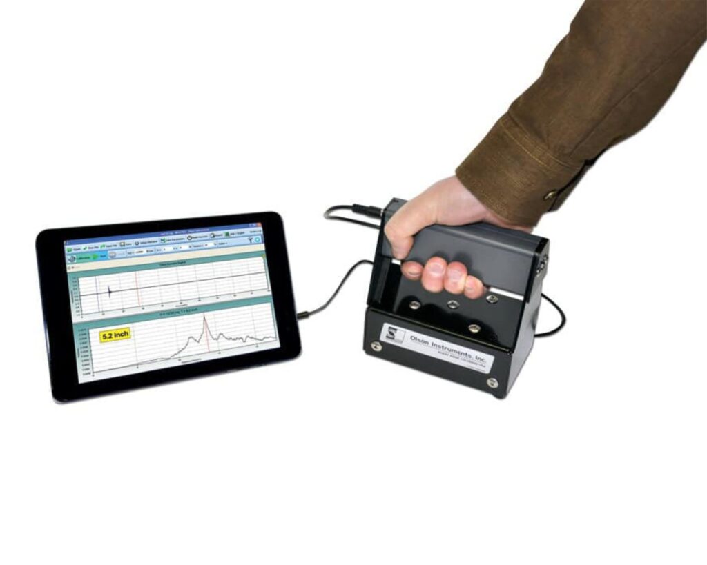
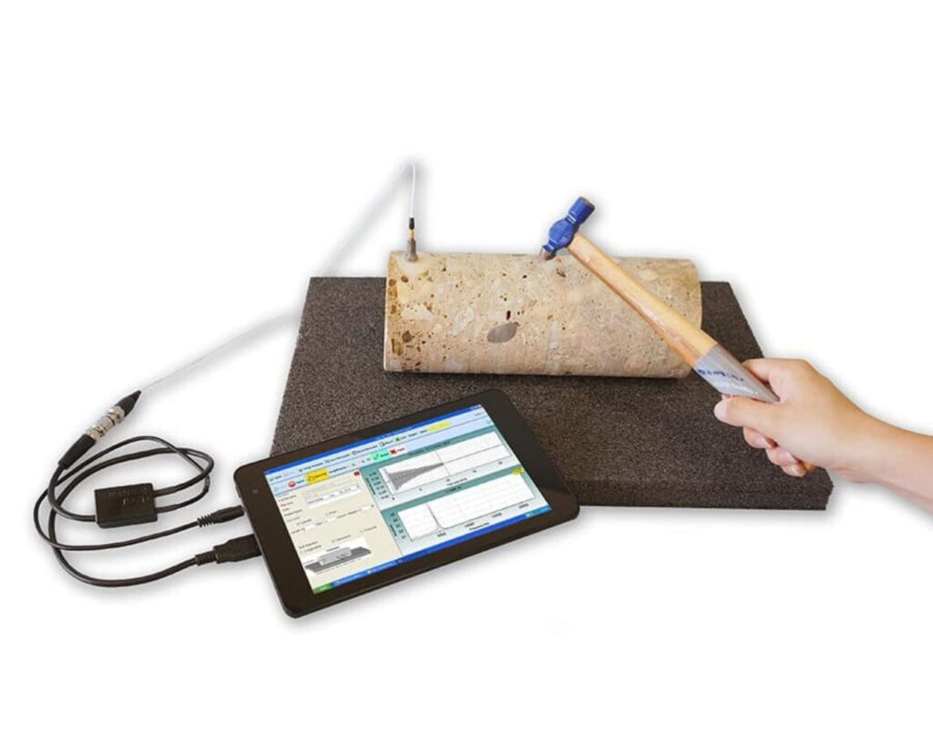
Concrete Thickness Gauge
Verify Concrete Slab Thickness & Integrity
No Coring — No Drilling — No Excavating
The Concrete Thickness Gauge (CTG-2) is a hand-held, battery powered, nondestructive system for measuring the thickness and integrity of concrete slabs, pavements, tunnel linings, walls and other plate-like structures using the IMPACT ECHO principle.
Requires no special knowledge or training — connect the Concrete Thickness Gauge to your laptop or tablet* and start testing with Olson’s WinCTG2 software. For greater accuracy, simply calibrate the CTG-2 by testing a point of known concrete thickness to obtain the concrete velocity for that job.
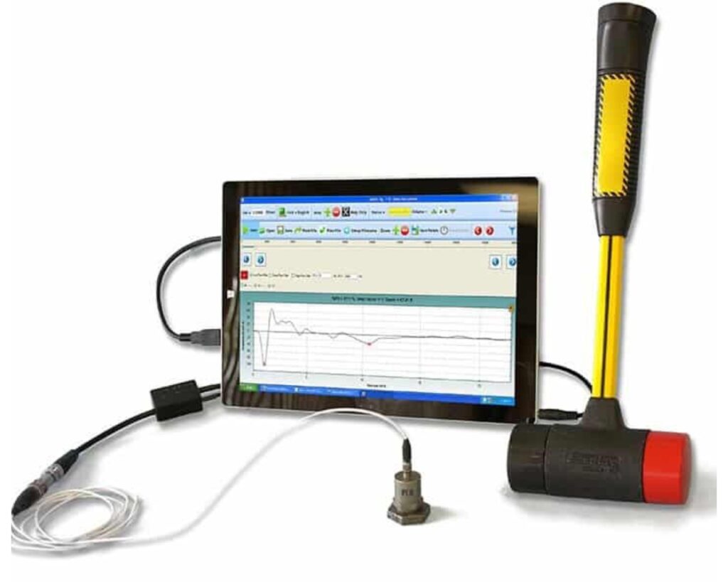
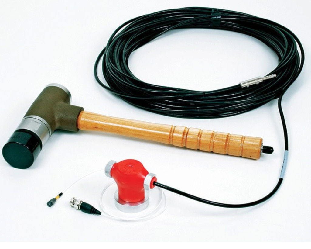
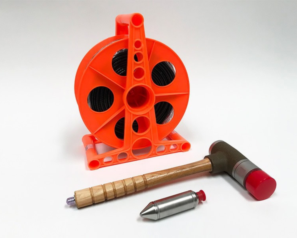
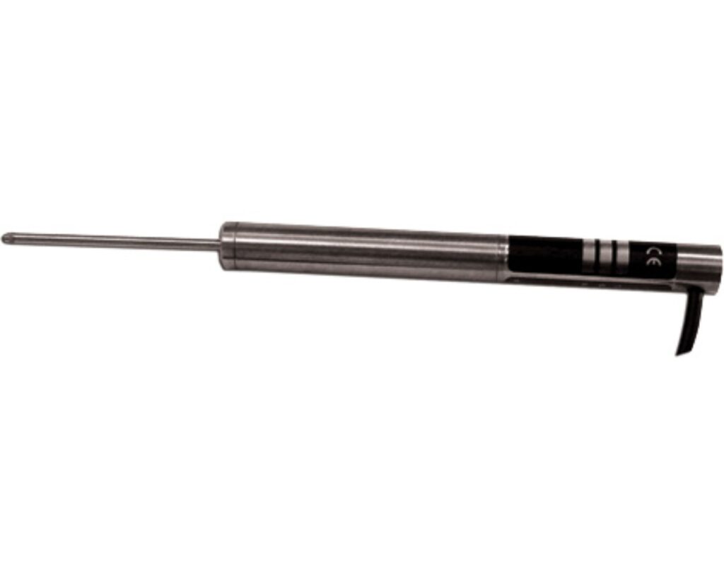
Foundation Test Gauge
The Foundation Test Gauge (FTG) is a small laptop or tablet powered, nondestructive system for measuring the depth and integrity of drilled shafts, driven piles, concrete mats, and timber foundations using the SONIC ECHO principle (also called Pile Integrity Testing or PIT, Low Strain Integrity, and other names).
Requires only minimal training for use — connect the Foundation Test Gauge to your laptop or tablet and start testing with Olson’s FTG software. The system includes everything you need for testing except for a user-provided Windows 7 – 10 laptop or tablet – including an accelerometer receiver and a non-instrumented hammer.
Resonance Test Gauge
The Resonance Test Gauge system is typically used to measure the dynamic Young’s modulus (E), shear modulus (G) and Poisson’s ratio (ν) of asphalt, concrete, rock, masonry, carbon and other cylinder, beam, and core-shaped specimens. This system meets the ASTM C215 standard for resonance testing of concrete for dynamic properties and freeze-thaw durability testing (ASTM C666). A sample spreadsheet [+] for all moduli calculations for longitudinal, flexural and torsional tests is included in this package.
The Resonance Test Gauge must be used with a Windows 7-10 device running Olson Instruments’ RTG software.
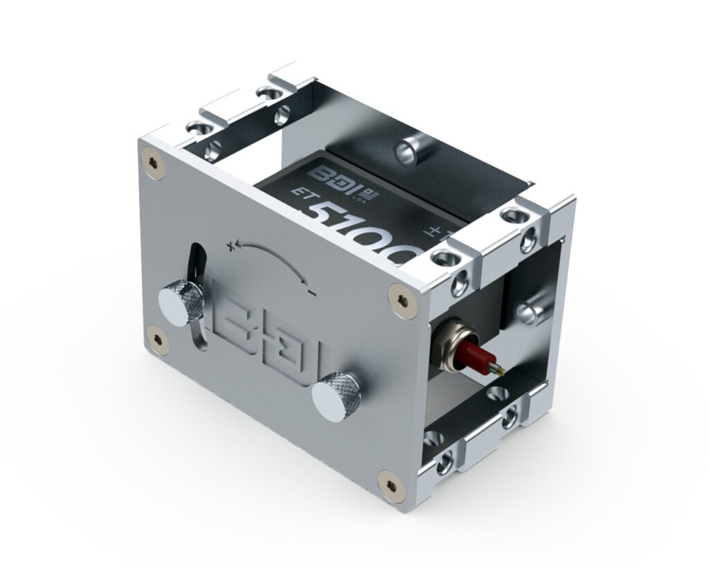
Linear Variable Differential Transformer (LVDT)
The Linear Variable Differential Transformer (LVDT) displacement transducer accurately measures the movement between the spring-loaded sliding armature and the exterior body. These rugged and self-contained units are ideal for recording displacements on structural members due to live loads and temperature variations.
With years of experience using these transducers on bridges, building and hydraulic structures they are the gold standard when it comes to very accurate position measurements.
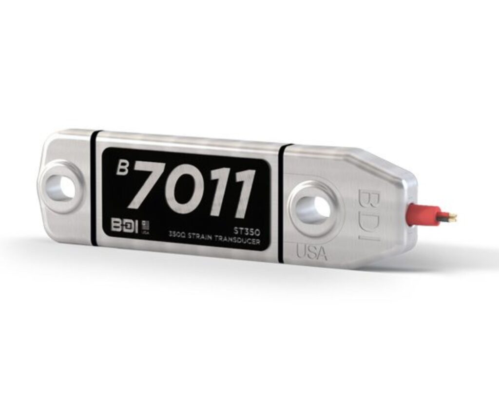
Strain Transducer
BDI Strain Transducer is the gold standard in structural health monitoring, which promises the fastest setup times and most reliable readings.
It is a resistive-based strain gage, made up of a 350ohm full Wheatstone bridge strain transducer to provide accurate, reliable, readings. Cable entry into the aluminum enclosure is fully potted for a weatherproof product that performs in the harshest of field environments. With roughly 3.5 times the output of a typical foil gage, these reusable sensors are ideal for measuring live-load strain.
These sensors are designed to be the most rugged and easy-to-use strain gages on the market, allowing you to install them in minutes in any weather condition. You can use this Strain transducer to measure strain on steel, concrete, reinforced concrete, fiber reinforced polymers, and timber with our full suite of accessories and mounting options.
Tiltmeter
Vibrating Wire Tiltmeter is designed to measure tilt in structures such as buildings, dams and embankments, and also for measurements related to the stability of slopes, open pits, and the walls of excavations (e.g. slurry walls). The tiltmeter is permanently attached to the structure to be monitored and can make measurements on horizontal or vertical surfaces.
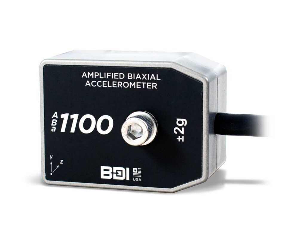
Accelerometer
Amplified accelerometer has been designed for dynamic structural testing in tough field conditions. These accurate, rugged, and fully-weatherproofed integrated MEMS sensors can be used from zero to medium frequency applications that require low noise and reliable long-term stability.
Available in uniaxial, biaxial, and triaxial configurations with ±2g, ±5g, ±10g, ±25g and ±50g sensitivity options. The sensors are made-to-order with your choice of cable length. A non-amplified version, It is also available for cable lengths under 300ft.
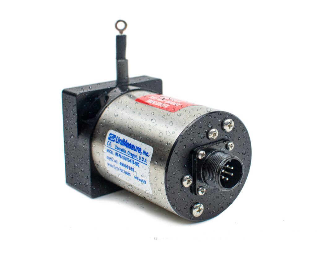
Cable Potentiometer
Cable Potentiometer (CPOT) is a specialized displacement sensor designed to measure large movements on structures with moving components, such as highway moveable bridge spans and river control lift gates. The device utilizes a spring-loaded cable spool to deliver infinite resolution across selectable measurement ranges from 1.0 to 80 inches, and it can be configured with either a voltage or 4-20mA output. Engineered to facilitate quick and easy installation in any mounting orientation, it features a highly durable, corrosion-resistant stainless steel housing.
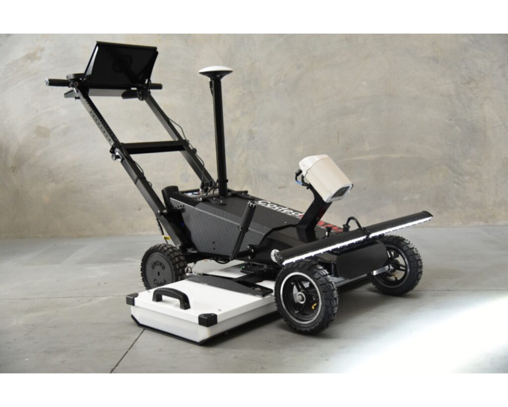
Push-Cart 3D Noise Modulated-GPR
The Lynx is a compact, high-performance push-cart platform designed for high-resolution 3D subsurface and surface imaging in a single walk-behind pass. It utilizes proprietary Noise-Modulated Ground Penetrating Radar (NM-GPR) technology to capture data thousands of times faster than traditional GPR, entirely bypassing the depth and speed compromises of conventional systems. The platform comes equipped with a built-in PC, flexible data positioning options (including RTK-GNSS, robotic total stations, or grid-based scanning), and an optional storable line-scan surface imaging camera with an integrated lighting array. Designed for total field mobility, the system features a fold-away or removable light array to allow for effortless transport across rugged job sites. It functions as a powerful, ultra-precise tool for geotechnical investigations, utility mapping, concrete deck inspections, and localized urban site context surveys where GPS signals may be unreliable.
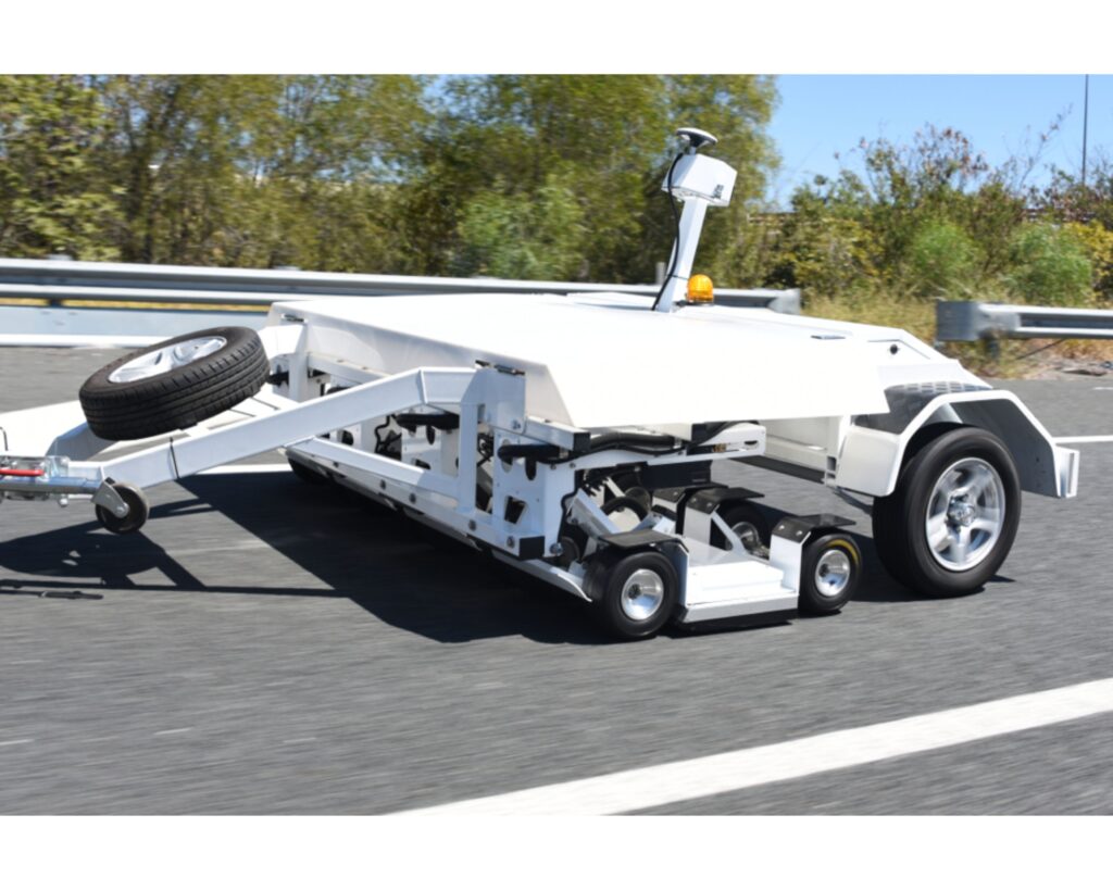
Traffic-Speed 3D Noise Modulated-GPR
The Kerberos is a vehicle-mounted, heavy-duty utility platform engineered to execute high-density 3D NM-GPR surveys at highway traffic speeds without disrupting public road networks. By employing an array-based design, it rapidly gathers overlapping 2D GPR profiles that are cross-correlated to map extensive subsurface volumes covering roads, bridge decks, and airport runways in their entirety. Simultaneously, it leverages integrated auxiliary sensors—including transverse lasers for rutting, inertial measurement units (IMUs), roughness measurement modules (IRI), and photometric stereo vision—to capture synchronized surface defect data. This high-speed capability ensures maximum field crew safety while capturing fine-grained structural data across the sensitive 960–1610 MHz frequency spectrum. The resulting multi-layered datasets allow infrastructure engineers to definitively match underground void developments directly with corresponding surface failures in a holistic model.